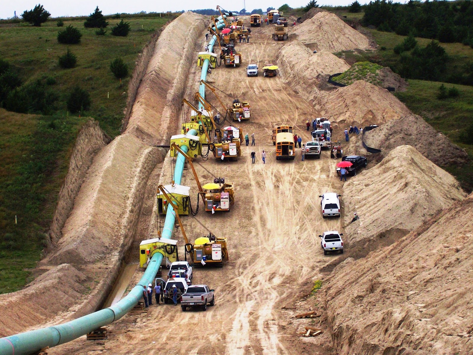
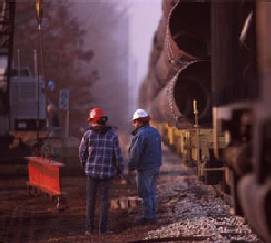
Saturday, July 19, 2014

PIGGING - Pipeline Inspection & Safety


PIGGING - PIPELINE INSPECTION AND SAFETY
"Smart pigs are intelligent robotic devices that are propelled down pipelines to evaluate the interior of the pipe."pipeline_inspection_tool

IN LINE INSPECTION (ILI) - SMART PIGS

“Inline inspection (ILI) tools, also referred to as smart or intelligent pigs, are devices 
that are propelled by the product in the pipeline and are used to detect 
and characterize metal loss caused by corrosion.

ILI tool launchers and receivers must be added to the pipeline. 
They are the most widely accepted method of inspection of pipelines due to its ability to measure wall thickness with near 100 percent coverage of the pipe inspected. 

Present regulations are focused on pipelines in “high-consequence areas” (HCAs)...because of a high-population density or a great environmental impact.”

Source:
"In order to ensure the efficient and safe operation of the extensive network 
of natural gas pipelines, pipeline companies routinely inspect their pipelines 
for corrosion and defects. This is done through the use of sophisticated pieces 
of equipment known as ‘smart pigs.’ 

Smart pigs are intelligent robotic devices that are propelled down pipelines
 to evaluate the interior of the pipe. 


Smart pigs can test pipe thickness, and roundness, 

check for signs of corrosion, detect minute leaks, 

and any other defect along the interior of the pipeline 
that may either impede the flow of gas, 
or pose a potential safety risk to the operation of the pipeline. 

Sending a smart pig down a pipeline 

is fittingly known as ‘pigging’ the pipeline.


Source: Natural Gas - Transport - Pipeline Inspection & Safety


In-Line Inspection (Smart Pigs)

“Inline inspection (ILI) tools, also referred to as smart or intelligent pigs, are devices 
that are propelled by the product in the pipeline and are used to detect and characterie metal loss caused by corrosion.”
There are two primary types of ILI tools: magnetic flux leakage (MFL) tools 
and ultrasonic tools (UT). The more advanced ILI tools (high-resolution tools) 
are capable of discriminating between internal and external corrosion. 
MFL tools measure the change in magnetic flux lines produced by the defect and produces a signal that can be correlated to the length and depth of a defect.
In recent years, the magnetics, data storage, and signal interpretation 
have improved, resulting in improved mapping of the flaw and a decrease 
in the number of unnecessary excavations. 
The high-resolution MFL tool is typically capable of readily detecting corrosion
pits with a diameter greater than three times the wall thickness. 
Once detected, these tools can typically size the depth of the corrosion within +10 
percent of the wall thickness with an 80 percent level of confidence. 
The MFL tool can be used to inspect either liquid products pipelines or natural 
gas pipelines. 
UT tools utilize large arrays of ultrasonic transducers to send and receive soundwaves that travel through the wall thickness, permitting a detailed mapping of the pipe wall. UT tools can indicate whether the wall loss is internal or external. The typical resolution of a UT tool is +10 percent of the pipe wall thickness with an 80 percent level of confidence. UT tools are typically used in products pipelines (e.g., crude oil, gasoline, etc.) since the product in the pipeline is used as the required couplant for the ultrasonic sensors. This tool can be used to inspect natural gas pipelines, but requires introducing a liquid (i.e., water) into the pipeline for transporting the ILI tool through the line. 
Source: DNVUSA - GAS & LIQUID TRANSMISSIN PIPELINES
By Neil G. Baker


V A L V E S


"These large valves can be placed every
5 to 20 miles along the pipeline." 


ground_valve


"Interstate pipelines include a great number of valves along their entire length. 

These valves work like gateways; they are usually open and allow natural gas to flow freely,
or they can be used to stop gas flow along a certain section of pipe. 

There are many reasons why a pipeline may need to restrict gas flow in certain areas. 

For example, if a section of pipe requires replacement 
or maintenance, valves on either end of that section of pipe 
can be closed to allow engineers and work crews safe access. 

These large valves can be placed every 5 to 20
 miles along the pipeline, and are subject to regulation by safety codes.

Source: Natural Gas - Transport - Valves


COMPRESSOR STATIONS

C O M P R E S S O R   S T A T I O N S
EVERY 10 - 40 MILES TO PUSH GAS OVER MTNS
42" COMPRESSOR STATIONS in RUSSIA both photos by gazprom.com
42" PIPELINE CONSTRUCTION IN PLAINS OF NEBRASKA
both photos by procegregory.com
                              
                                       WETZEL COUNTY WV  Compressor Station

compressor_station


                                          Source: Duke Energy Gas Transmission Canada


"Natural gas is highly pressurized as it travels through an interstate pipeline. 
To ensure that the natural gas flowing through any one pipeline remains 
pressurized, compression of this natural gas is required periodically along the pipe. 
This is accomplished by compressor stations, usually placed at 
40 to 100 mile intervals along the pipeline. The natural gas enters the compressor station, where it is compressed by either a turbine, motor, or engine.

Turbine compressors gain their energy by using up a small proportion 
of the natural gas that they compress. The turbine itself serves to operate 
a centrifugal compressor, which contains a type of fan that compresses 
and pumps the natural gas through the pipeline. 

Some compressor stations are operated by using an electric motor 
to turn the same type of centrifugal compressor. This type of compression 
does not require the use of any of the natural gas from the pipe, 
however it does require a reliable source of electricity nearby. 

Reciprocating natural gas engines are also used to power some compressor stations. 
These engines resemble a very large automobile engine, 
and are powered by natural gas from the pipeline. 
The combustion of the natural gas powers pistons on the outside of the engine, 
which serves to compress the natural gas.

LIQUID SEPARATORS

CLEAN AIR COUNCIL PRESENTATION for Durbin WV 8-7-14 
AERIAL VIEWS HELICOPTERS - TRANSMISSION PIPES 

L I Q U I D  S E P A R A T O R S
WITHIN COMPRESSOR STATIONS EVERY 10-40 MILES
ARE LIQUID SEPARATORS
As the pipeline enters the compressor station the natural gas passes 
through scrubbers, strainers or filter separators. 
These are vessels designed to remove any free liquids or dirt particles 
from the gas before it enters the compressors. 
Though the pipeline is carrying “dry gas,” 
some water and hydrocarbon liquids may condense 
out of the gas stream as the gas cools 
and moves through the pipeline.  

Any liquids that may be produced are collected 
and stored for sale or disposal.  
A piping system directs the gas from the separators 
to the gas compressors.
SOURCE: INGAA - Interstate Natural Gas Association
Photo:INGAA
"In addition to compressing natural gas, compressor stations 
also usually contain some type of liquid separator, 
much like the ones used to dehydrate natural gas during its processing. 
m

Usually, these separators consist of scrubbers and filters 

that capture any liquids or other unwanted particles 
from the natural gas in the pipeline. 


Although natural gas in pipelines is considered ‘dry’ gas, 

it is not uncommon for a certain amount of water 
and hydrocarbons to condense out of the gas stream 
while in transit. 


The liquid separators at compressor stations ensure 

that the natural gas in the pipeline is as pure as possible, 
and usually filter the gas prior to compression.

Source: Natural Gas - Transport - Compressor Stations

METERING STATIONS

CLEAN AIR COUNCIL PRESENTATION for Durbin WV 8-7-14 
AERIAL VIEWS HELICOPTERS - TRANSMISSION PIPES 
M  E T E R I N G   S T A T I O N S
EVERY 2 - 5 MILES - HELICOPTERS CHECK FOR LEAKS

  
"In addition to compressing natural gas to reduce its volume 
and push it through the pipe, metering stations are placed 
periodically along interstate natural gas pipelines. 
These stations allow pipeline companies to monitor 
the natural gas in their pipes. 
Essentially, these metering stations measure the flow of gas 
along the pipeline, and allow pipeline companies to ‘track’ 
natural gas as it flows along the pipeline. 
These metering stations employ specialized meters 
to measure the natural gas as it flows through the pipeline, 
without impeding its movement."
Source: Natural Gas - Transport - Metering Stations


"Pipeline companies install VALVES along a gas pipeline system 
to provide a means of controlling flow.
The valves may be spaced as close together as 
EVERY FIVE MILES or as far apart as TWENTY MILES 
according to standards established by applicable safety codes.  
The valves normally are open, but when a section of pipeline requires maintenance, operational engineers close the valves to isolate that section of the pipeline.  
Once isolated, the maintenance crew can vent the gas from that section of the pipeline and proceed with its work.
SOURCE: Interstate Natural Gas Association of America [INGAA]


TRANSMISSION PIPES


PIPES IN TRANSIT 
Source: Duke Energy Gas Transmission Canada

  "Mainline transmission pipes, the principle pipeline 
      in a given system, are usually 
      between 16 and 48 inches in diameter."
      Lateral pipelines, which deliver natural gas 
      to or from the mainline, 
      are typically between 6 and 16 inches in diameter. 
      Most major interstate pipelines are between 
      24 and 36 inches in diameter"


Transmission pipes can measure anywhere from 6 to 48 inches in diameter, depending on their function. Certain component pipe sections can even 
consist of small diameter pipe, as small as 0.5 inches in diameter. 

However, this small diameter pipe is usually used only in gathering and distribution systems. Mainline transmission pipes, the principle pipeline in a given system, are usually between 16 and 48 inches in diameter. Lateral pipelines, which deliver natural gas to or from the mainline, are typically between 6 and 16 inches in diameter. 

Most major interstate pipelines are between 24 and 36 inches in diameter. 

The actual pipeline itself, commonly called ‘line pipe’, consists of a strong carbon steel material, engineered to meet standards set by the American Petroleum Institute (API).  In contrast, some distribution pipe is made of highly advanced plastic, because of the need for flexibility, versatility and the ease of replacement. Transmission pipelines are produced in steel mills, which are sometimes specialized to produce only pipeline. 

There are two different production techniques, one for small diameter pipes and one for large diameter pipes. For large diameter pipes, from 20 to 42 inches in diameter, the pipes are produced from sheets of metal which are folded into a tube shape, with the ends welded together to form a pipe section. Small diameter pipe, on the other hand, can be produced seamlessly. This involves heating a metal bar to very high temperatures, then punching a hole through the middle of the bar to produce a hollow tube. In either case, the pipe is tested before being shipped from the steel mill, to ensure that it can meet the pressure and strength standards for transporting natural gas.

Line pipe is also covered with a specialized coating to ensure that it does not corrode once placed in the ground. The purpose of the coating is to protect the pipe from moisture, which causes corrosion and rusting. There are a number of different coating techniques. In the past, pipelines were coated with specialized coal tar enamel. Today, pipes are often protected with what is known as a fusion bond epoxy, which gives the pipe a noticeable light blue color. In addition, cathodic protection is often used; which is a technique of running an electric current through the pipe to ward off corrosion and rusting

Source: Natural Gas - Transport - Transmission Pipes